
Centrifugal Pump Selection: A Complete Engineering Guide
Why Proper Selection Matters
Selecting the right centrifugal pump is far more than matching numbers from a catalogue. It is a balanced engineering decision that directly impacts operational costs, system reliability, and equipment lifespan. Overlooking a single critical factor — whether it’s fluid behavior, suction conditions, or installation constraints — often results in excessive energy consumption, unstable performance curves, and unexpected downtime. This guide walks you through the entire selection process, from fluid analysis to long-term maintenance planning.
Operating Principle: Converting Energy into Flow
At its core, a centrifugal pump converts mechanical energy from the motor into hydraulic energy. The rotating impeller accelerates the incoming liquid outward, while the volute casing captures this high-velocity flow and transforms a portion of its kinetic energy into pressure energy, discharging the fluid into the piping system.
This technology excels at handling high flow rates in continuous duty cycles. However, reliable operation depends on two non-negotiable conditions: adequate suction supply and sustained operation close to the Best Efficiency Point (BEP).
Variables That Shape Pump Performance
Several design and operating parameters directly influence both efficiency and mechanical longevity:
- Impeller geometry — closed, semi-open, or open configurations
- Rotational speed and impeller diameter
- Material selection for wetted components
- Net Positive Suction Head (NPSH) and inlet piping layout
Understanding these variables is the first step toward making an informed decision.
Step 1: Characterize the Pumped Liquid
Fluid properties are the foundation of every selection. They determine not only performance but also the pump’s service life.
- Viscosity — higher viscosity increases internal friction and power demand, often reducing overall efficiency.
- Density — Affects pressure generation and mechanical stress on shafts and bearings.
- Corrosiveness and abrasiveness — Dictate suitable materials for the casing, impeller, and sealing system.
- Solids content — suspended particles accelerate wear and may cause clogging, requiring larger clearances or specialized impeller designs.
A comprehensive fluid assessment at the outset prevents most operational headaches downstream.
Step 2: Define Flow Rate and Head Requirements
These two parameters form the core of any pump specification:
- Flow rate (Q) — the volume of fluid delivered per unit of time
- Head (H) — the total hydraulic energy required to overcome elevation differences and system friction losses
The pump’s actual operating point is determined by the intersection of its characteristic curve and the system resistance curve. The ideal scenario places this point as close as possible to the BEP, where the pump runs smoothly and efficiently.
Step 3: Choose the Pump Orientation — Horizontal vs Vertical
The decision between horizontal and vertical configurations extends beyond available floor space.
| Aspect |
Horizontal Pumps |
Vertical Pumps |
| Installation |
Require more floor area but offer easier access |
Fit into compact footprints, ideal for sumps or confined spaces |
| Maintenance |
Simpler component access — motors and seals are at eye level |
May require specialized lifting tools for disassembly |
| Applications |
Standard industrial duties |
Deep wells, tanks, or applications with limited headroom |
Consider foundations, maintenance access, and future serviceability before finalizing the layout.
Step 4: Evaluate Temperature and Pressure Limits
Temperature and pressure are interdependent parameters that affect both materials and seal integrity:
- Elevated temperatures may degrade elastomers, alter fluid viscosity, and reduce suction performance.
- System pressure is directly linked to the required head but also depends on pipe diameter and wall thickness.
It is critical to keep the fluid below its vapour pressure at suction conditions to avoid cavitation. Always verify that selected materials are rated for the entire operating temperature range.
Step 5: Account for Environmental Conditions and Solids
External factors often receive insufficient attention, yet they heavily influence long-term reliability:
- Ambient conditions — High humidity or dust levels may require motors with enhanced protection (IP ratings) and corrosion-resistant enclosures.
- Solids in suspension — Increase turbulence, elevate wear rates, and can cause imbalance, leading to vibration and noise.
The right pump for harsh environments often incorporates hardened materials, oversized shafts, and wear-resistant coatings.
Component Breakdown: Anatomy of a Centrifugal Pump
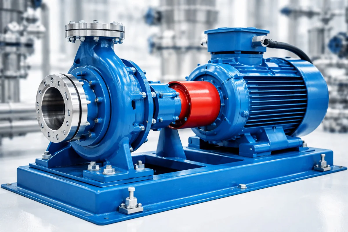
A standard centrifugal pump consists of several key components working in concert:
- Suction flange — fluid entry point
- Discharge flange — pressurized fluid exit
- Volute casing — converts velocity to pressure
- Impeller — the rotating element that imparts energy (available in closed, semi-open, or open designs)
- Mechanical seal or packing — prevents leakage along the shaft
- Shaft and bearings — transmit torque and support rotation
- Drive motor — provides prime mover power
- Baseplate or mounting frame — ensures alignment and stability
The impeller is often considered the “heart” of the pump — its geometry and material directly dictate performance, efficiency, and durability.
Material Selection Guide for Impellers
Choosing the correct impeller material is a critical decision that balances cost against operating conditions:
| Material |
Best Suited For |
Key Limitation |
| Stainless Steel |
Corrosive fluids, food processing, seawater |
Higher initial cost |
| Bronze |
Fresh water, marine applications, mild chemicals |
Not suitable for strong acids |
| Aluminium |
Lightweight applications, low-temperature water |
Poor corrosion resistance |
| Engineering Plastics (PP, PVDF) |
Acids, solvents, aggressive chemicals |
Limited to moderate temperatures and pressures |
Always cross-reference material compatibility charts with your actual fluid composition.
How to Perform Accurate System Sizing
Sizing transforms raw data into a reliable pumping solution. The goal is to avoid:
- Oversizing — leads to wasted energy, throttling losses, and reduced motor efficiency
- Undersizing — results in inadequate flow, overheating, and premature mechanical failure
A comprehensive sizing procedure includes:
- Plotting the system curve — head versus flow, incorporating elevation and friction losses
- Determining total dynamic head (TDH) from suction lift to discharge pressure
- Calculating friction losses for both suction and discharge piping
- Adjusting for temperature-induced changes in viscosity and vapour pressure
- Verifying NPSHa (available) exceeds NPSHr (required) by a safe margin
Many systems unknowingly drift away from their optimal curve. Regular monitoring of pressure gauges and flow meters helps detect deviations and allows timely corrections.
Maintenance Strategy for Sustained Performance
Efficiency doesn’t end with installation — it requires ongoing attention. A well-structured preventive maintenance programme should include:
- Lubrication management — regular checks of bearing oil levels and condition
- Impeller cleaning — removal of scale, debris, or polymer buildup
- Seal replacement — timely swapping of worn mechanical seals or packing
- Shaft alignment verification — misalignment is a leading cause of vibration and bearing failure
- Vibration and temperature trending — early detection of imbalance or overheating
Modern control panels can integrate sensors for real-time condition monitoring, enabling predictive maintenance and minimising unplanned plant shutdowns. When paired with automated alarms, these systems ensure your pump station remains stable, efficient, and cost-effective over its entire lifecycle.
Beijing XLHJ International delivers full-cycle support — from expert selection to timely supply of centrifugal pumps, providing efficient solutions for a wide range of industries and applications.