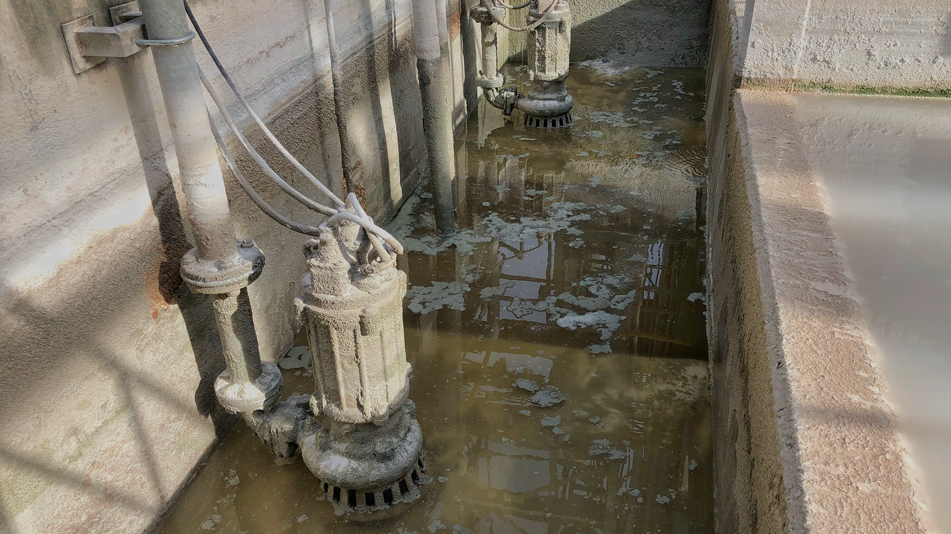
Submersible Borehole Pumps for Industrial Applications: Engineering Selection, Material Science & Lifecycle Optimization
1. Scope and Industrial Context
This guide is intended for project engineers, procurement specialists, and technical maintenance personnel involved in industrial water supply, mine dewatering, irrigation districts, thermal power plant cooling circuits, and offshore platform utilities.
Unlike residential systems, industrial submersible borehole pumps operate continuously (24/7/365), often under variable voltage conditions, aggressive water chemistry, and high solids content. The primary objective is not minimum purchase price, but maximum mean time between failures (MTBF) and lowest lifecycle cost (LCC) .
2. Pump Classification and Hydraulic Design
Industrial submersible borehole pumps are multi-stage centrifugal units with vertically stacked impellers and diffusers. The number of stages (typically 3 to over 50) determines the total dynamic head (TDH). Key design parameters:
- Specific Speed (Nₛ): Determines impeller geometry (radial, mixed-flow, or axial). For borehole applications, radial or low-specific-speed mixed-flow impellers are standard to achieve high heads with moderate flow.
- Hydraulic Thrust: In multi-stage pumps, the cumulative axial thrust can reach several tons. This is compensated by:
- Balance discs or balance drums (active thrust compensation)
- Heavy-duty angular contact thrust bearings (oil-lubricated or water-lubricated)
- Motor Configuration: The motor is flange-coupled to the hydraulic section. For industrial duty, only NEMA or IEC frame motors with Class F/H insulation and IP68 rating are acceptable.
3. Material Selection (Critical for Industrial Environments)
Material choice directly determines pump survival in aggressive media. We categorize by water quality:
| Water Condition |
pH Range |
Chlorides (ppm) |
Recommended Metallurgy |
| Clean / Fresh |
6.5 – 8.5 |
< 200 |
AISI 304L or 316L (shafts, impellers, bowl) |
| Slightly aggressive |
5.5 – 6.5 or 8.5 – 9.5 |
200 – 1000 |
AISI 316L + duplex stainless steel for shaft |
| Highly aggressive / saline |
< 5.5 or > 9.5 |
> 1000 |
Super duplex (UNS S32750) or Ni-resist cast iron; shaft – Inconel 625 or titanium |
| Abrasive (sand ≥ 100 g/m³) |
any |
any |
Hardened stainless steel (400 series) or stellite-faced wear rings; ceramic-coated impellers |
Other critical components:
- Rubber parts: NBR (for petroleum-free water) or EPDM (for ozone/UV-treated water); FKM/Viton for high-temperature (>70°C) or aggressive chemicals.
- Fasteners: A4-80 austenitic stainless steel (not A2) to avoid crevice corrosion in chloride-rich environments.
4. Selecting the Pump: Step-by-Step Engineering Methodology
Step 1 – Determine the Well Performance Curve (WPC)
Obtain the well step-drawdown test results. The pump must operate below the maximum sustainable yield (MSY) of the well. Operating above MSY will cause rapid drawdown, cavitation, and motor overheating due to insufficient submergence.
Step 2 – Calculate Total Dynamic Head (TDH)
TDH = (Static Water Level + Drawdown + Surface discharge elevation) + Friction losses (pipe + fittings) + Discharge pressure head.
Important: For industrial systems with long horizontal pipelines (≥ 500 m), friction losses often exceed vertical lift. Use Hazen-Williams or Darcy-Weisbach with proper roughness coefficient (for steel/HDPE pipes).
Step 3 – Select Operating Point on Pump Curve
- The selected pump must have its Best Efficiency Point (BEP) within ±15% of the system curve intersection.
- Avoid operation to the far right (overload zone) – it causes excessive axial thrust and bearing overheating.
- Avoid operation to the far left (low flow) – it causes recirculation, vibration, and reduced motor cooling.
Step 4 – Check NPSH (Net Positive Suction Head) Available vs. Required
For submersible pumps, NPSHA is determined by the submergence depth. Ensure that NPSHA is at least 0.5 – 1.0 m higher than NPSHR (from the pump curve) to prevent cavitation, which erodes impellers and damages bearings.
5. Motor and Power Supply Engineering
For industrial installations, motor selection is not trivial:
- Low-voltage (LV) motors: 380–690 V, 50/60 Hz, suitable for power up to 200 kW.
- Medium-voltage (MV) motors:3 kV, 6 kV, or 10 kV for high-power units (>200 kW). MV pumps require specialized junction boxes and pothead connectors.
- Cooling: In industrial settings with high solids or low water velocity, use of a motor shroud (cooling jacket) is mandatory. The shroud forces a minimum downward flow velocity (≥ 0.3 m/s) across the motor surface.
- Variable Frequency Drives (VFDs): Strongly recommended for industrial applications. VFDs allow:
- Soft-start (reduces mechanical shock)
- Flow/pressure regulation without throttling valves (energy saving up to 30%)
- Constant pressure operation under varying water levels
- Protection against overcurrent and phase imbalance
Important: When using VFDs, the motor must be designed for inverter duty (with reinforced insulation to withstand voltage spikes). Motor cable length and shielding must be calculated to avoid reflected wave phenomena.
6. Key Industrial Accessories and Protection Systems
| Component |
Purpose |
| Motor protection relay (MPR) |
Monitors current, voltage, phase sequence, and thermal load. Trips on overload, dry-run, or phase failure. |
| Pressure transmitter (4–20 mA) |
Provides continuous feedback to VFD for closed-loop pressure control. |
| Flow meter (electromagnetic or ultrasonic) |
Measures actual output; critical for performance monitoring and well yield tracking. |
| Non-return valve (flap or swing type) |
Installed above the pump; prevents water hammer when pump stops. |
| Surge arrestor / bladder tank |
Absorbs pressure surges during pump start/stop. |
| Check valve with bleed port |
Allows slow drainage to prevent sand settling on impellers during downtime. |
| Cable hanger and torque arrestor |
Prevents cable twisting and abrasion against casing. |
7. Installation Engineering (Industrial Specifics)
- Installation depth: At least 3 m below the dynamic water level (to avoid vortex formation), but never closer than 2 m from the well bottom (to avoid sediment intake).
- Pump alignment: Verticality must be maintained within 1° to prevent excessive bearing wear on long shaft assemblies.
- Cable sizing: Voltage drop must not exceed 5% at full load. For long drop cables (>200 m), voltage drop calculations must consider motor starting current (6–8× FLC).
- Grounding: A dedicated grounding conductor is mandatory for industrial safety. Grounding resistance ≤ 4 Ω.
- Wellhead sealing: Industrial installations require explosion-proof (Ex) or weather-proof (IP66) wellhead enclosures, depending on the hazardous zone classification.
8. Operation Monitoring & Predictive Maintenance
Industrial pumps cannot rely on reactive maintenance. We recommend an Industry 4.0 approach:
- Vibration monitoring (accelerometers): Detect bearing wear, impeller imbalance, or cavitation at early stages.
- Motor winding temperature (RTD sensors): Monitored in real-time; alarm at 130°C, trip at 150°C (Class F insulation).
- Power consumption analysis: Any increase in specific energy (kWh/m³) indicates hydraulic degradation or scaling.
- Oil sample analysis (for oil-filled motors): Check for water ingress (dielectric breakdown) and particle count.
Maintenance schedule for industrial duty:
- Monthly: Check electrical insulation resistance (MΩ) – should be > 20 MΩ.
- Quarterly: Calibrate pressure transmitters and flow meters.
- Bi-annually: Pull pump for visual inspection of impellers, wear rings, and shaft straightness.
- Annually: Replace thrust bearing oil (if oil-lubricated) and check mechanical seal integrity.
9. Common Industrial Failure Modes and Prevention
| Failure |
Root Cause |
Preventive Measure |
| Motor burnout |
Dry-running, voltage unbalance > 5%, high ambient temperature |
Install dry-run protection, use VFD with phase monitoring, derate motor for high temps |
| Impeller erosion |
Sand concentration > 150 g/m³ or large particles |
Install sand trap / desander before pump; use hardened impellers |
| Shaft breakage |
Excessive thrust due to pump operating far from BEP |
Adjust impeller trim or VFD frequency to bring operation within BEP zone |
| Corrosion / pitting |
Chloride-induced stress corrosion cracking (SCC) |
Upgrade to super duplex or Ni-resist; monitor chlorides regularly |
| Water ingress to motor |
Failed mechanical seal (due to sand or dry-run) |
Use dual mechanical seals with pressure monitoring between seals |
10. Life Cycle Cost (LCC) Analysis – Why Initial Price Is Misleading
For industrial customers, LCC is calculated as:
LCC = Purchase Price + Energy Cost (over N years) + Maintenance Cost + Downtime Cost.
Energy typically represents 70–85% of the total LCC over 10 years. A pump that is 3% more efficient, but 15% more expensive upfront, pays back within 1.5–2 years and then saves significant operational expenditure. Therefore, we recommend always selecting pumps with at least MEI ≥ 0.7 (Minimum Efficiency Index) and operating as close to BEP as possible.
Technical Support and Commercial Partnership – Beijing XLHJ International
Selecting the right industrial submersible pump is a complex multi-parameter task that requires not only theoretical knowledge but also practical experience with local water conditions, power supply characteristics, and operational constraints. This is where Beijing XLHJ International provides tangible value to your project.
Our engineering support includes:
- Free hydraulic selection: We analyze your well test data, required flow-head curve, and site conditions (ambient temperature, altitude, power quality) to recommend the optimal pump model and motor power rating.
- Material compatibility check: Based on your water analysis report (pH, chlorides, TDS, sand content), we propose the most cost-effective metallurgy — from standard 304L to super duplex or Ni-resist — ensuring maximum service life without over-engineering.
- VFD and control system configuration: We calculate the required drive size, cable cross-section, and protection relay settings tailored to your specific motor and site distance.
Commercial advantages for industrial buyers:
- Direct factory pricing: As a direct supplier of Chinese-manufactured industrial pumps, we eliminate intermediary markups. You pay for the hardware and engineering support, not for brand premiums.
- Customized solutions: Non-standard voltages (e.g., 460V/60Hz for American markets, 380V/50Hz for Europe/Asia, or 6kV/10kV medium-voltage motors) are available on request without extra engineering charges for standard modifications.
- Spare parts availability: We maintain a dedicated spare parts inventory for all supplied models, ensuring minimal downtime for your operations.
- Transparent quality assurance: Every pump undergoes factory hydrostatic testing, motor insulation resistance test, and performance curve verification before shipment. Test reports are provided with each delivery.
Our commitment: We do not just sell pumps; we provide a complete pumping solution backed by technical expertise. Whether you are developing a new mine site in Africa, upgrading irrigation infrastructure in Latin America, or replacing aging equipment in a European industrial plant, our team ensures you receive the most reliable and cost-effective equipment for your specific application.
📧 Contact Beijing XLHJ International for a technical consultation and commercial quote tailored to your project requirements.






 22.10.2026